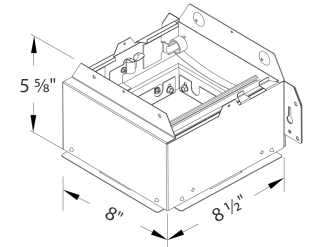
Ceiling Radiation Damper Cad Detail

Pottorff Mobile

Dayton Ceiling Radiation Damper Duct Size In 11 1 8 In Height In 13 1 2 In Width In 3dpf9 3dpf9 Grainger
Free Hvac Revit Download Breezintegrity Itg Crd Ceiling Radiation Damper Bimsmith Market

Pottorff

Air Conditioning System Components Mechanical Room Duct Work Air Conditioning System

Pottorff Mobile
A 12 x 12 305mm x 305mm nominal ceiling radiation damper could have a maximum ceiling membrane opening of 13 x 13 330mm x 330mm.
Ceiling radiation damper cad detail.
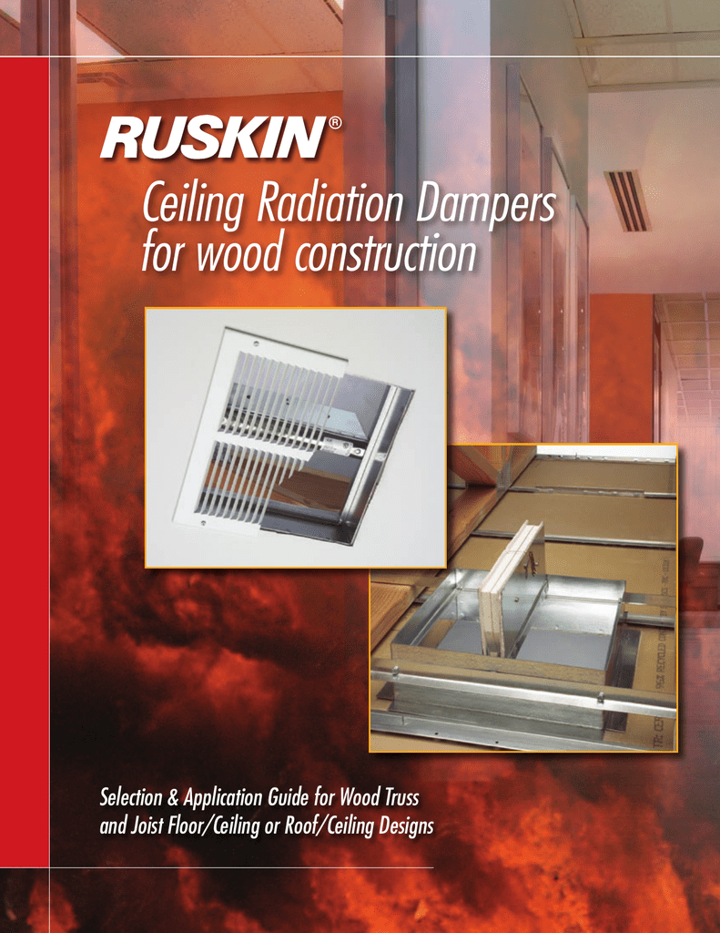
Ceiling Radiation Dampers For Wood Construction

Pottorff Mobile

Pottorff Mobile

Broan Ceiling Radiation Damper 12 1 2 Height In 12 1 2 Width In 3 5 8 Depth In 4tr64 Rd1 Grainger
Source : pinterest.com
